Everybody Staze...

Nobody leavz...

  • Home
  • About Me
    • LinkedIn
    • Lab
  • Contact
  • Links
  • Reviews
  • Sitemap
  • Weather

Genie Garage Door remote upgrade

2014/06/24 By staze

GIRUD-1T
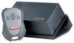
Just a short post: When we bought our house, it came with a 1992 or so, vintage Genie Garage Door opener that used the old dip switch style remote code. I recently found a GIRUD-1T conversion kit at the local Goodwill for $5, and figured I’d convert it, but in the process you want to remove the old controller, or at least clip the antenna.

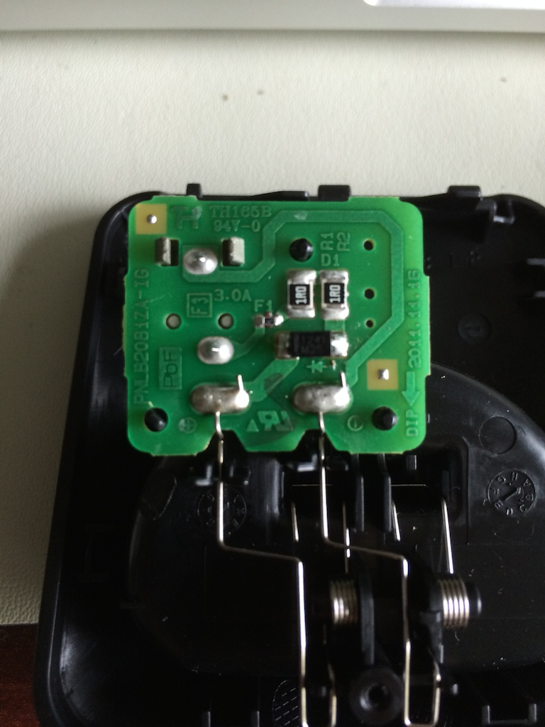
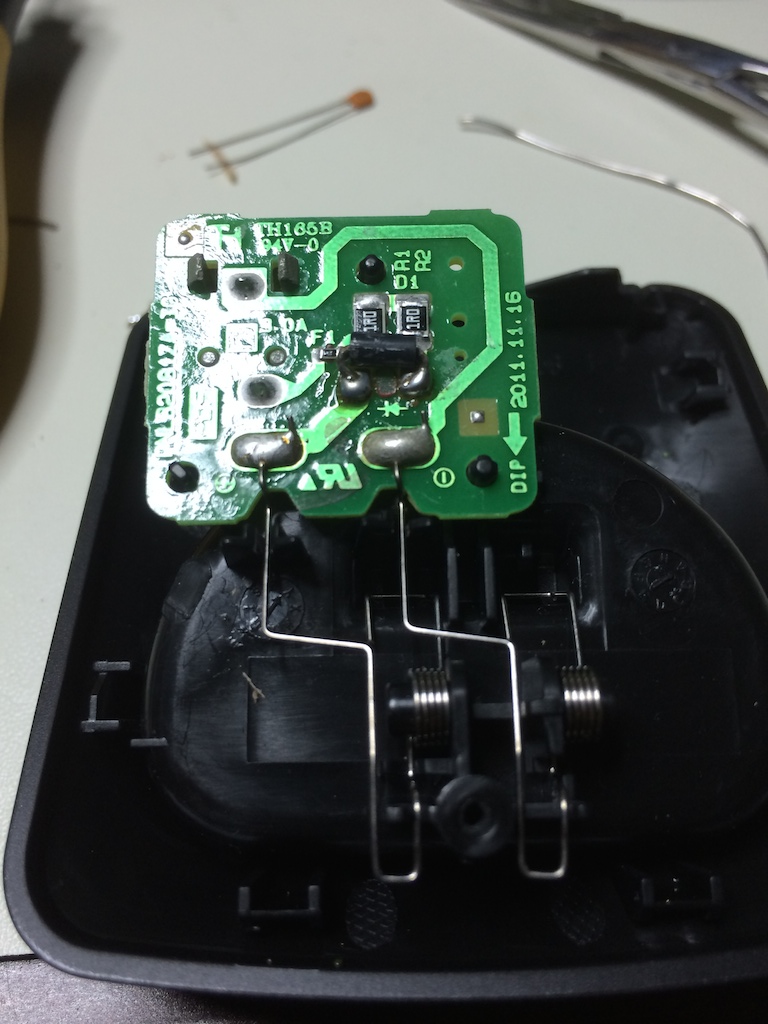
When I opened the unit, I saw the remote board was only held in by one screw, and had a simple 3 wire header wire hooked to it (more on this in in a moment). Upon opening up the “box” that the GIRUD came in, I noticed the board was the same size, but had screw terminals on it… but it also had the PCB holes for a header. Genie are pragmatic! The conversion kit was literally just the exact same controller that they’d put in an opener, in an enclosure! I took both units, removed the screw terminals from the new on, and move the header over. The only caveat is that the 3 pin connector will go on upside down from the previous board (ground toward the top, vs ground toward the bottom).

After that, it was just screw the new board in, and hook it up. Worked great (new board actually has a relay that audibly clicks when it gets a good remote signal). If curious, the GIRUD board is packaged with a 24VAC adapter that is for power. But, if you look at the board, they’ve just implemented a half-wave rectifier (capacitor and diode) to give DC to the board. Giving it 24VDC is no problem, then.

Of interest to those that are curious, the pin header has a Vcc (Purple), GND (Green), and Trip (Black) connections. When the remote control receiver gets a good signal, and wants to open the door, it grounds the Trip wire, which then tells the controller to open the door. Otherwise, that pin just floats.

Pretty simple project, and avoids the extra wiring and ugly box on the ceiling. Now, I think I’m going to see if I can create some type of code scanner with the old remote and receiver to see JUST how insecure those old openers are. =)

Filed Under: Electronics Tagged With: Garage Door, Genie, GIRUD-1T, Intellicode

2nd Fluke 87 True RMS Multimeter Repair

2014/06/21 By staze

Fluke 87
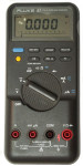
Just posting a quite note that I recently purchased another Fluke 87 from eBay, this time at a more rational price of $75, with a fading display. With the wonderful help of Mr. Modemhead’s detailed explanation, I was able to get the screen back to factory quality, and the unit looks brand new!

Also cleaned up the yellow rubber boot with another page he published here. Meter looks brand new, took me maybe 25 minutes to do the screen repair. I’m pretty darn happy. I now have a Fluke 8060a, 87, and 189… I’m not sure they’re all considered the same family, but that’s how I’m going to look at it. =)

Filed Under: Electronics Tagged With: Fluke 87, Multimeter, repair

Repairing Panasonic PNLC1029

2014/06/21 By staze 120 Comments

Panasonic PNLC1029 BoardI purchased a set of Panasonic cordless phones from woot.com a while back, and all of them worked great. But, after a while, one of the chargers stopped working. Looking at the voltage on the charger, it was showing the normal voltage across it (about 5.5V), but the unit just wouldn’t charge. I wired up the unit with my meter between checking amperage draw, and it was only pulling about 2mA, where a working charger showed 200mA. Hmmm…

I opened the charger (single screw on the bottom) and it’s pretty darn simple, as you can see from the picture. The 1R resistors both checked out, as did the fuse, but interestingly, I was seeing a 1.8V drop across the protection diode. That’s… not right. I opened another unit and got the normal 0.6V drop across it.

So, figured the diode might be bad, I pulled it, and got the more normal 0.6V drop. So, bad solder joint it would have seemed. I put it back in, and soldered it back in, and it stayed with the 0.6V drop. I hooked it all back up, and meter showed a more normal 200mA draw. So, it works!

Obviously, given the look of the board, I’m guessing these are cranked out by the thousands, and just ended up with a cold solder. So if you have one of these, check that protection diode (as well as the fuse), since it’s unlikely the resistors would go south. =)

PNLC1029 1N4001UPDATE 7/3/2014As can be told from the comments, I’ve had the repair fail since doing it. Resoldering the diode would help for a bit, then it would fail again. So, knowing the diode was the issue, I grabbed a standard axial 1N4001 from the parts bin, trimmed the legs, bent them over, and soldered it in place. So far, it’s working… but I’m not going to consider it fixed until it lasts for a good month or so. I have to wonder, since I can’t find any stats on that diode, if it’s overheating (and therefore, under-spec, but that generally wouldn’t cause the symptoms seen). And yes, I know it looks like hell. I don’t care. =)

Filed Under: Electronics Tagged With: Panasonic Charger, repair

« Previous Page
Next Page »

Weather

Categories / Archives

  • Apple
  • Coding
  • Electronics
  • Energy
  • Home Ownership
  • Miscellany
  • Politics
  • Prius
  • Sys Admin
  • Travel
  • Uncategorized
  • Work
  • April 2026
  • August 2025
  • April 2025
  • January 2024
  • February 2021
  • July 2020
  • January 2020
  • April 2019
  • March 2018
  • February 2018
  • June 2017
  • February 2017

Copyright © 2026 · Staze On Genesis Framework · WordPress · Log in