 I purchased a set of Panasonic cordless phones from woot.com a while back, and all of them worked great. But, after a while, one of the chargers stopped working. Looking at the voltage on the charger, it was showing the normal voltage across it (about 5.5V), but the unit just wouldn’t charge. I wired up the unit with my meter between checking amperage draw, and it was only pulling about 2mA, where a working charger showed 200mA. Hmmm…
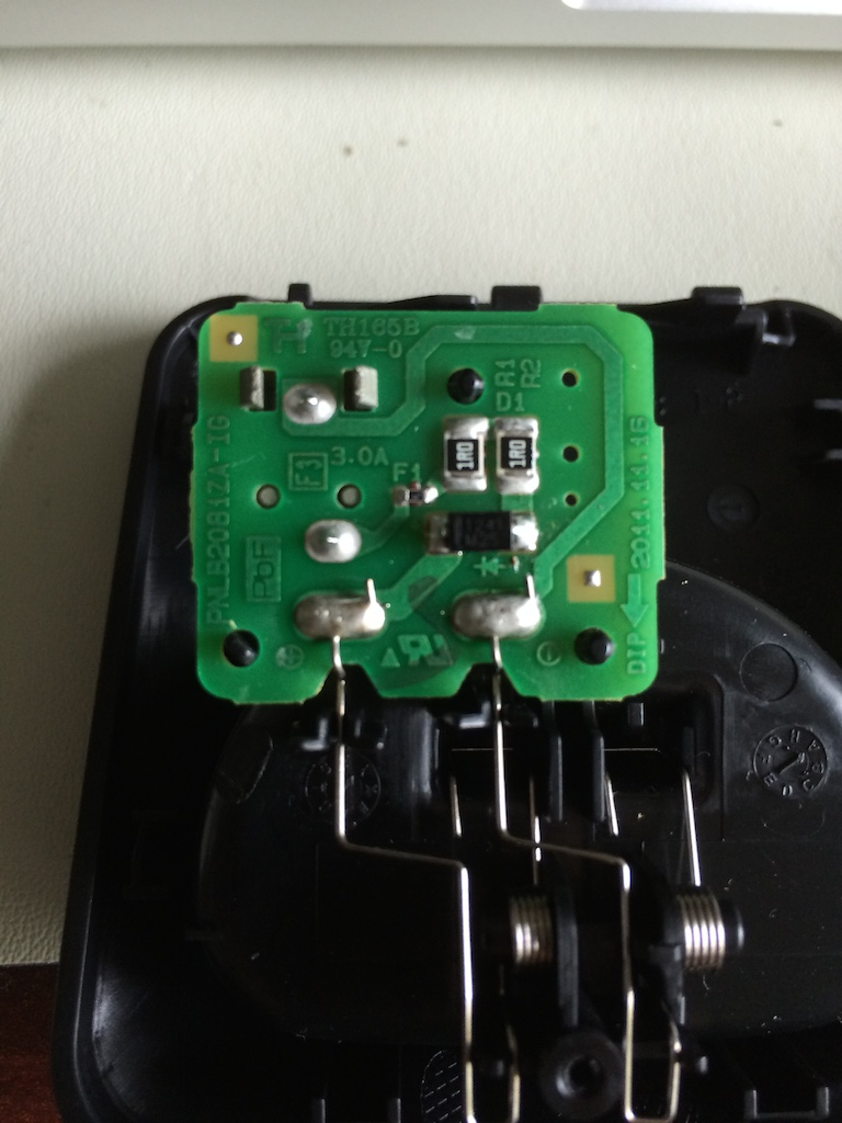
I opened the charger (single screw on the bottom) and it’s pretty darn simple, as you can see from the picture. The 1R resistors both checked out, as did the fuse, but interestingly, I was seeing a 1.8V drop across the protection diode. That’s… not right. I opened another unit and got the normal 0.6V drop across it.
So, figured the diode might be bad, I pulled it, and got the more normal 0.6V drop. So, bad solder joint it would have seemed. I put it back in, and soldered it back in, and it stayed with the 0.6V drop. I hooked it all back up, and meter showed a more normal 200mA draw. So, it works!
Obviously, given the look of the board, I’m guessing these are cranked out by the thousands, and just ended up with a cold solder. So if you have one of these, check that protection diode (as well as the fuse), since it’s unlikely the resistors would go south. =)
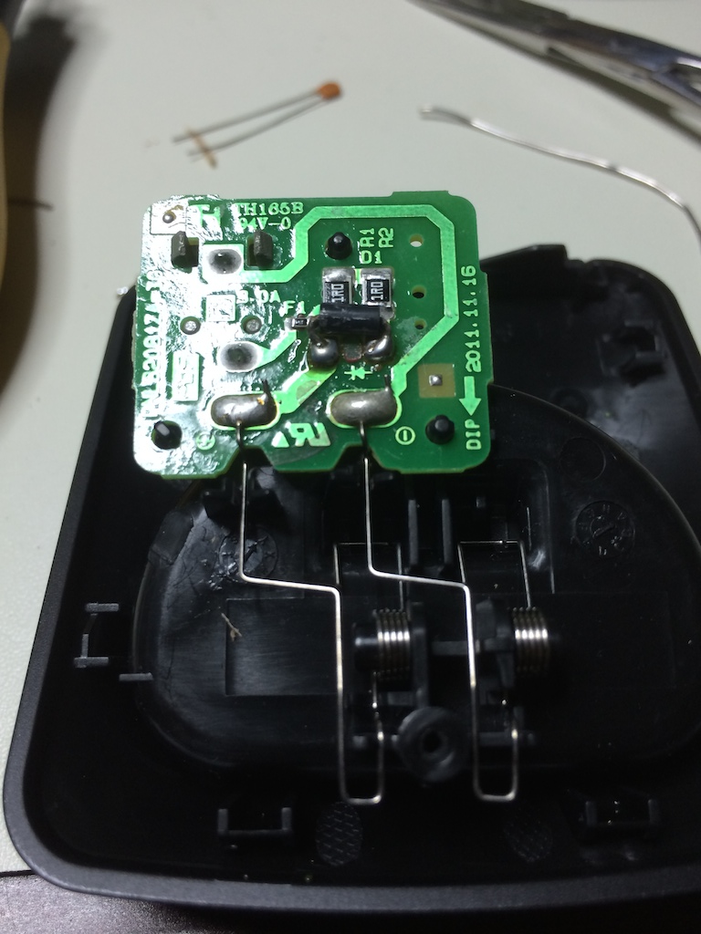 UPDATE 7/3/2014As can be told from the comments, I’ve had the repair fail since doing it. Resoldering the diode would help for a bit, then it would fail again. So, knowing the diode was the issue, I grabbed a standard axial 1N4001 from the parts bin, trimmed the legs, bent them over, and soldered it in place. So far, it’s working… but I’m not going to consider it fixed until it lasts for a good month or so. I have to wonder, since I can’t find any stats on that diode, if it’s overheating (and therefore, under-spec, but that generally wouldn’t cause the symptoms seen). And yes, I know it looks like hell. I don’t care. =)