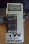
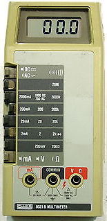
 Knowing no end to my suffering, I realized I enjoyed repairing a friends Fluke 8021B so much, that I bought my own off eBay for $20 and decided to repair it. Checking the meter out before the repair, everything seemed to work just fine, including the historically amazing continuity beeper ((the whole reason I bought it, since it has a trigger time of 50µs (that’s 50 micro-seconds, or 0.00005 seconds). Meaning it only has to see continuity for that long before the beeper sounds. So you can quite literally sweep along an IC pretty fast to find which pin may/may not have continuity to your test point. Thankfully, there’s also a pulse stretcher that means even if you only have continuity for those 50µs, the beeper will sound for at least 200ms.)) ((And yes, theoretically the 8060a has a faster beeper, but… okay, fine, I’m a meter collector, and I couldn’t turn down an 8021B for $20.)).
Fender Frontman Reverb Repair
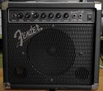
 Ages and ages ago, a coworker brought me his Fender Frontman Reverb amp saying it didn’t work. He had a second one that did work, so there wasn’t any rush to get it working, so I took the unit home, and went to work on it. Disassembly was easy enough, and finding the schematics showed that the unit was identical to the Fender Frontman 15R, which has schematics (in the service manual) here. The US Fender site SAYS it has schematics for the 15G-15R, but only the 15G is shown, meaning the whole reverb section is left out. =/
Fluke 8021B LCD Repair
 A coworker recently gave me his Fluke 8021B to repair as it had taken a fall ages ago, and the LCD had been damaged. Having seen a post ages ago on Mr. Modemhead’s site, I knew repairing the screen on the 8020A was doable, and figured the 8021B would be identical as far as screen.
The problem, actually, is the LCD holder is surprisingly different (much more sturdy). So after I ordered and received the LCDs, I went about “machining” the LCD holder to let it fit. This took grinding off part of the “top” where the pins would lay, and several other ribs to allow the LCD to sit “flat” on the holder ((As noted later, I actually didn’t do enough the first go around)). Wiring the LCD, I used two colors of 30AWG wire, and a wire wrap tool (that I hadn’t used before). I used two colors of wire to help differentiate between the bottom and top pins. I also, breaking from Mr. Modemhead’s page, drilled small holes in the LCD holder to feed the “bottom” wires through, and to help keep them in order. Stripping the wires, then soldering to the PCB was annoying, but not overly time consuming. I also had to re-solder the “COM” jack on the unit since it had worked loose enough to “spin”. This is very easy to do, as you just put the soldering iron IN the jack, let the whole thing get nice and hot, and then touch solder to the bottom side, then the top side, and let it cool. I did have to “machine” the plastic of the top case a bit to let it clear the new solder, but it worked just fine, and was now solid. =)