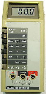
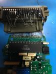
 A coworker recently gave me his Fluke 8021B to repair as it had taken a fall ages ago, and the LCD had been damaged. Having seen a post ages ago on Mr. Modemhead’s site, I knew repairing the screen on the 8020A was doable, and figured the 8021B would be identical as far as screen.
The problem, actually, is the LCD holder is surprisingly different (much more sturdy). So after I ordered and received the LCDs, I went about “machining” the LCD holder to let it fit. This took grinding off part of the “top” where the pins would lay, and several other ribs to allow the LCD to sit “flat” on the holder ((As noted later, I actually didn’t do enough the first go around)). Wiring the LCD, I used two colors of 30AWG wire, and a wire wrap tool (that I hadn’t used before). I used two colors of wire to help differentiate between the bottom and top pins. I also, breaking from Mr. Modemhead’s page, drilled small holes in the LCD holder to feed the “bottom” wires through, and to help keep them in order. Stripping the wires, then soldering to the PCB was annoying, but not overly time consuming. I also had to re-solder the “COM” jack on the unit since it had worked loose enough to “spin”. This is very easy to do, as you just put the soldering iron IN the jack, let the whole thing get nice and hot, and then touch solder to the bottom side, then the top side, and let it cool. I did have to “machine” the plastic of the top case a bit to let it clear the new solder, but it worked just fine, and was now solid. =)
 Testing worked perfectly, and I put the unit back together. Noting there was a bit of purple on the bottom of the LCD, I checked to see if the case was putting pressure on it by applying pressure in that general area (to see if the color changed at all). I was greeted by an unpleasant “snap” and a blackened screen. =( Crap.
Try two, thankfully I’d ordered more than one screen. First step was to machine away more of the LCD holder to allow the LCD to sit fully flat on the holder. Yay, more plastic dust. =/ I also decided to use less wire to wrap the pins, then solder the wire to the pins to get good contact (and prevent any unwinding). I then heavily bent the pins on the “bottom” under the holder so that they no longer came in contact with the capacitors that sit under the LCD. I also hot-glued the wires to the underside of the LCD holder to keep them up off the CPU (and add some “stress” relief). Soldering was still a pain, but it didn’t cause too much of a problem, and re-installation was much easier this time since the LCD didn’t “hit” anything. Testing again worked great, and the whole unit felt much more “stock”, and no signs of pressure on the screen at all. I used some plastic polish on the lens, and the unit looked great!
Gave it back to my friend and got a reel of 3D filament in exchange. Score for both of us!

j says
do you have part number (digikey, etc) for lcd replace for 8021b? the lcd is pin-less flat glass with fingers on top
in plastic holder. the id on part is SF 344 H 12.01 D. if you have supply $/details ??
staze says
It’s not a direct replacement, but is explained in my post.
https://www.digikey.com/product-detail/en/lumex-opto-components-inc/LCD-S3X1C50TR-B/67-1790-ND/469778
Digikey Part: 67-1790-ND