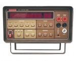
 I just came across an interesting “real world” example of multimeter burden voltage. I have a nifty USB voltage/amperage tester that I was using to measure the voltage/current/power draw of my iPhone 5s connected to one of those rechargeable battery power packs, and I kept seeing the phone, after some time, would report “accessory not supported” and stop charging. For the life of me, I couldn’t figure out why ((this is largely because I wasn’t paying attention to the meters all the time, so I didn’t notice the pattern right away)). The setup was running the battery pack into the USB tester, then to the phone. The USB Tester was plugged into my two Keithley 196’s, one measuring voltage, the other, current. Both were set to auto range ((you might see where this is going now, if you’re paying attention)). When you first plugin the phone, it would draw about 3/4 of an amp. It would then slowly draw less and less as the charge got higher and higher on the phone. Then at some point, it would stop charging.
USB Tester 2.0
 I have been looking for an easy way to monitor USB voltage and power used by devices, and while there are numerous cheap usb inline adapters to do this, and a few people that just show how to cut a USB cable so you can probe the lines, I thought both of these seemed a bit weak. Then, looking around Tindie.com one day, I found the USB Tester 2.0. It’s a very simple PCB, and some pin headers. The advantage is it provides easy voltage/current monitoring, but also provides an easy way to probe the data lines with a scope. Plus, it isn’t ugly (like a hacked USB cable would be).
I ordered the “kit” on a Friday (along with the Plexiglass base), and it was shipped from California the same day. Somehow USPS opened a wormhole, and I got the kit the next day (Saturday). Assembly was extremely straight forward via the instructions here. Took maybe 5 minutes, at most (including time for the soldering iron to warm up). Initially, I was a bit confused by the pin header holes being a bit offset from each other, but it seems to was done on purpose to hold the pin header in place for soldering, which is awesome.
Anyway, once assembled, the units work as expected. The only problem I’ve seen is that the 4mm “jacks” are a little smaller than 4mm, it seems. My dual banana plugs don’t quite fit fully. I’m actually thinking of installing some real jacks on the unit, so things will fit, but I am not sure they’ll fit very well, or not block the rest of the unit. =/ Hopefully I’ll figure something out, as I’d like to be able to use banana plugs without worrying about ruining the PCB holes.
All and all, very happy with the unit. It does what I wanted it to do, and maybe in the future I’ll buy the OLED “pack” that basically makes the unit self-contained and won’t require a meter.
[xrr rating=4.75/5]